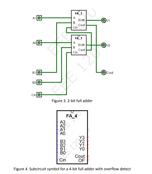


Using a test-bench module, verify if the 3-bit full adder works correctly by showing its operation for the following combinations.Note: you will have to use instances of the half and full adders for this purpose. Using the Verilog codes for full and half adders implement the 3-bit full adder circuit. Draw a block diagram of a 3 bit-adder using half and full adders.You can use EP Wave to demonstrate the results. Using test bench modules, verify if the full adder work correctly. Mainly there are two types of Adder: Half Adder and Full Adder. Here is a brief idea about Binary adders.
#2 bit half adder truth table chegg code#
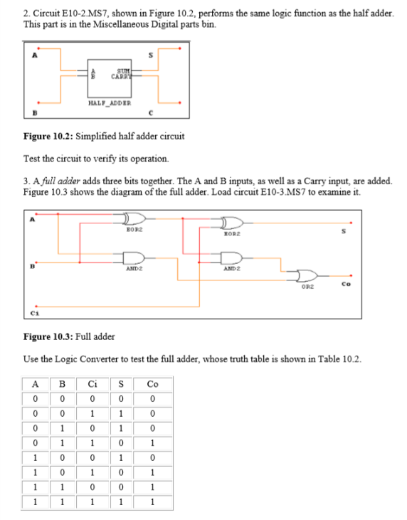
implement the Verilog code for full adder using half adder code implemented in the previous step. In previous tutorial of half adder circuit construction, we had seen how computer uses single bit binary numbers 0 and 1 for addition and create SUM and Carry out.Today we will learn about the construction of Full-Adder Circuit.Draw the full adder circuit using half adders and an OR gate.The augent and addent bits are two input states, and 'carry' and 'sum 'are two output states of the half adder. The adder is used to perform OR operation of two single bit binary numbers. Using a decoder add a seland the needed components to be able to select whether your design acts as. The Half-Adder is a basic building block of adding two numbers as two inputs and produce out two outputs. Design a 4-bit adder using the half adders. You can use EP Wave to demonstrate the results Using Table 1, write a Verilog program to implement a decoder that selects the proper input to the full adder depending on the selsignal.

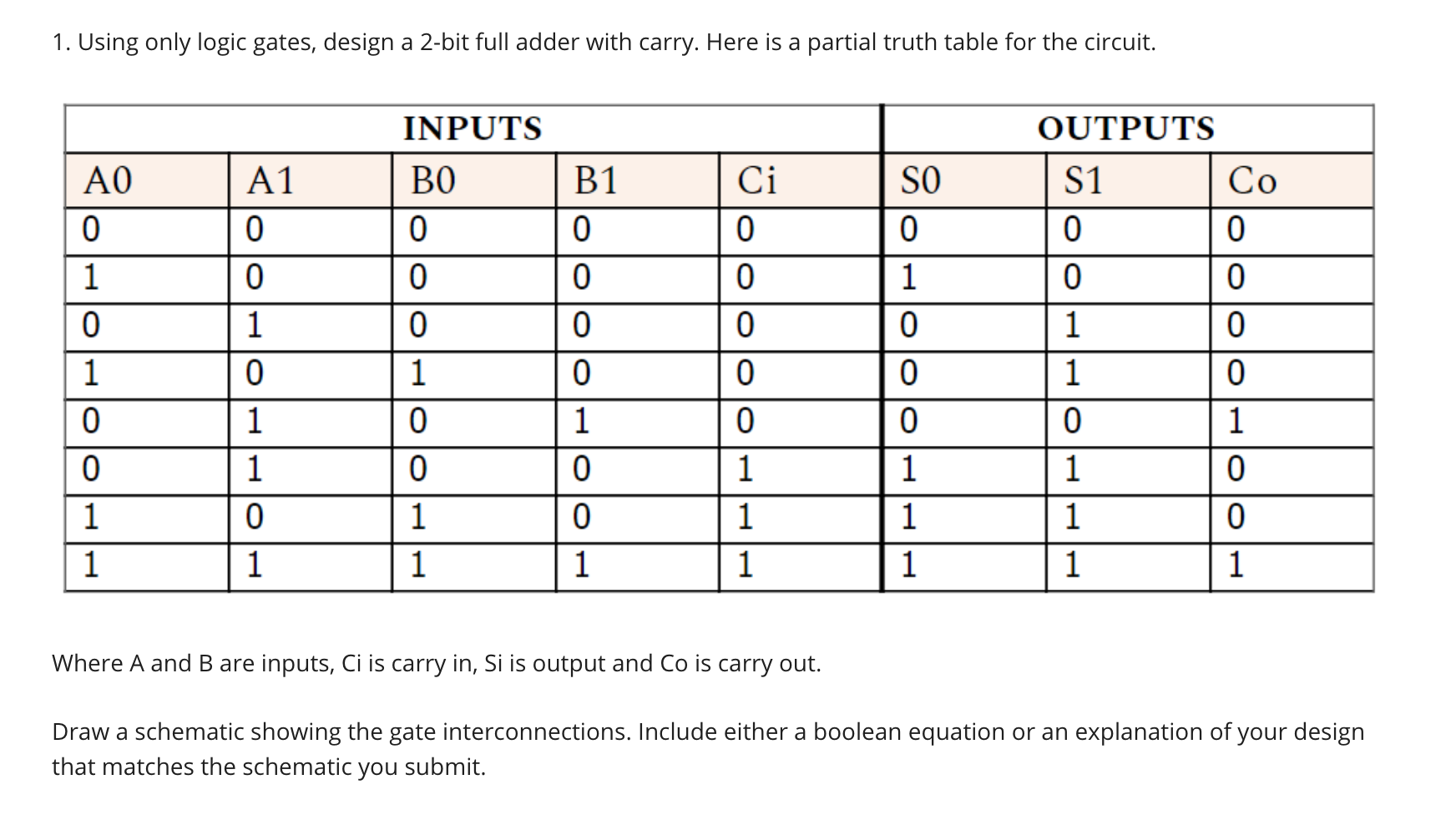
Using test bench modules, verify if the half adder code works correctly. Transcribed image text: Question 5: Design a half adder circuit (2 pts) Complete the truth table below.


 0 kommentar(er)
